Draw a Shape the exact size and shape as the image you want to be transparent. Stay open for 00050 seconds 3.

Cam Follower Motions Engineering Drawing Joshua Nava Arts
Assuming that the cam is stationary mark in a series of positions of the line of stroke.

. The follower moves in a plane perpendicular to the axis of. Again tape tracing paper over your plot plan and go back to your list of needs from step two. How To Draw Cam.
The mechanism of Cam and Follower is essential in the engineering field and has many different functions to the different machines. 3 Decide the type or feel of the motion you want for your cam. Open a valve 005 inches in 00025 seconds 2.
For a knife-edge BJCS Cam Profile Drawer is an application that can be used to drawer cams with a graph and manipulate it in many ways. How far do they NEED to move and how far are they ABLE to move. How to execute in MATLAB.
1 Determine the constraints of the cam and follower. Make accelerations as small as possible. How to Develop a Cam Profile.
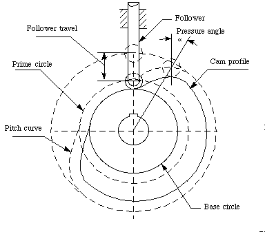
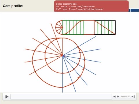
A cam is a device that changes the rotary motion of the camshaft into linear motion of the follower or filter. 3 Along each radial line plot the Y ordinates from the graph and at each point draw a 20 mm circle to represent the roller. When the flanks of the cam connecting the base.
Select a point in the drawing to specify the center of the cam and to insert the cam mechanism. Diagram and place space needs. The path of the tracer point.
This must be done at a scale of 11 to use it to generate the cam profile. Useful links UPSC books. During design of cam profile considered contact between cam follower and cam profile are ensured basically at two areas as base circle and nose.
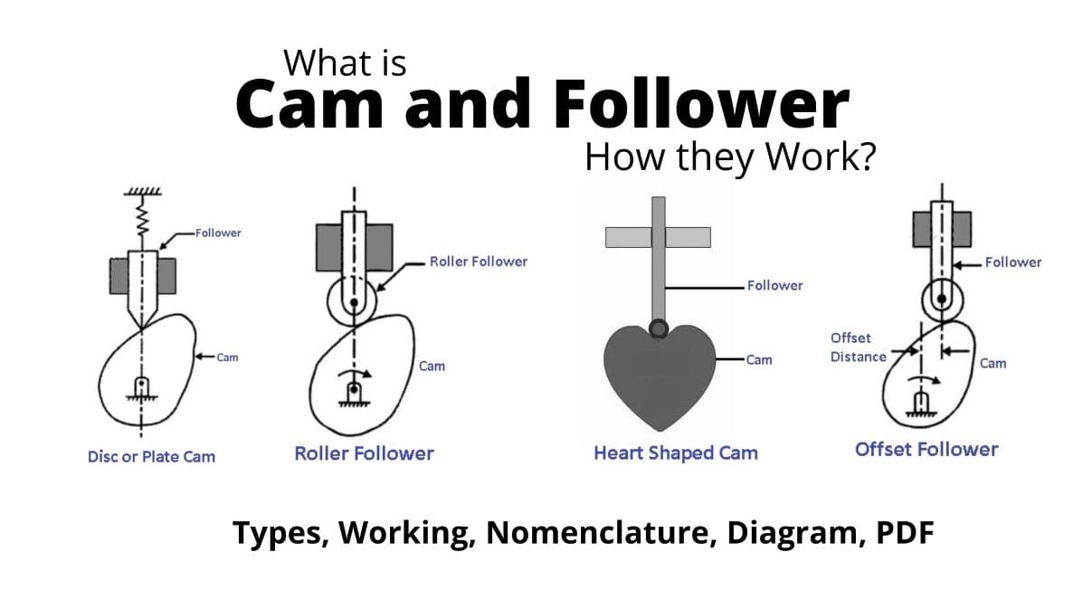
A CAM has two parts the FOLLOWER and the CAM PROFILE. The size of the base circle determines the. Close in 00025 seconds and 4.
This action will open the Format Ink page. PLATE CAM OR DISC CAM. This paper reviews the past and present research work in the field of kinematic and dynamic aspect of design and optimization of Cam profiles.
In some engines it is placed on the cylinder head. Take the line joining cam center and pivot point as reference and draw lines indicating successive angular displacements of cam. The following terms are important in order to draw the cam profile.
Eyes 03 how to draw a face. With the above given parameters a simulation run has been carried out when the cam profile is selected so as to generate a follower displacement x in the form. Draw another circle of radius equal to the distance between cam center and follower pivot point.
Where X is the follower maximum displacement ω is the cam angular velocity and ϕ. With the help of trace point we can detect the cam profile Steps to Draw a Gear- First the pitch circle addendum circle dedendum circle and root circle are drawn. How To Draw Cam Profile.
The contour of the working surface of the cam. It is the surface area of a cam where follower touches. For the knife-edge follower of the plate cam the pitch curve and the working curves coincide.
LUBRICATION OF THE CAM AND TAPPET INTERFACE The cam profile and the cam tappet interface are normally produced by grinding the surfaces. Httpsamznto3zWXHpXe-books for competitive exams. The camshaft is mounted on bearing in the lower part of the cylinder block most in-line engines.
How to draw a face. Heel nose Ramp opening closing Ramp. 2 Determine Base radius of cam.
2 x X abs sin ω t ϕ. The point at the knife edge of a follower or the center of a roller or the center of a spherical face. The Terminology of a Cam.
There are three main parts in a cam profile. A camshaft is only a shaft on which cams are installed. Stay closed for 002 seconds.
The cam follower needs to rise 50 mm and back to 0 mm for one cycle of the cam produce a graph using the following profiles. The working surface of a cam in contact with the follower. From a knowledge of the displacements in each of these positions and allowing for the type of follower to be used it is possible to draw the required profile of the cam See Examples 2 and 3.
2 years ago. This is the average height of the asperities on the surface. Construction of cam_profile physics101.
Should be observed by means of determination of cam profile. Draw base circle and prime circle. In a close or grooved cam there is an inner profile and an outer working curve.
Draw a cam follower displacement diagram for the following cam. Divide these into same number of divisions as in the displacement diagram. Two particular motions of the follower are frequently specified.
2 Draw a circle shown as RAD Q equal to the least radius of the cam plus the radius of the roller and divide it into 30 divisions. This controls the rest or starting position of the follower. The smallest circle drawn tangential to the cam profile with its center on the axis of the camshaft.
Design a cam system to. It is the smallest circle of a cam profile drawn from the center of rotation of the cam. 3 Along each radial line plot the Y ordinates from the graph and at each point draw a 20 mm circle to represent the roller.
1 Draw the cam graph as shown. Mark the camshaft angles in the anticlockwise direction. There are normally three or four steps in any CADCAM process.
This page contains information on how to draw ambigrams. More videos on cam profile here. Typically a simple grinding operation will produce the surface finish that is measured at 025 micron as a centre-line-average CLA.
2 005 yin t s 0 0 0001 00025 00075 0002 0003 Use a roller follower.

Cam And Follower Types Working Nomenclature Diagram Pdf

Cam Profile Profile How To Draw Cam Profile Cam Follower Kom Mechanical Youtube

How To Draw A Cam Profile Knife Edge Follower Part 4 Youtube
Chapter 6 Cams
How To Draw Cam Profile Complete Construction Part 3 Youtube
Cam Follower Motions Engineering Drawing Joshua Nava Arts

How To Draw A Cam Profile Knife Edge Follower Part 4 Youtube
Cam And Follower Types Working Nomenclature Diagram Pdf
0 comments
Post a Comment